

Why Winding Accuracy and Mechanical Integrity Matter
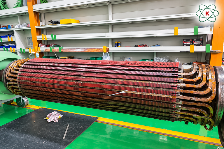
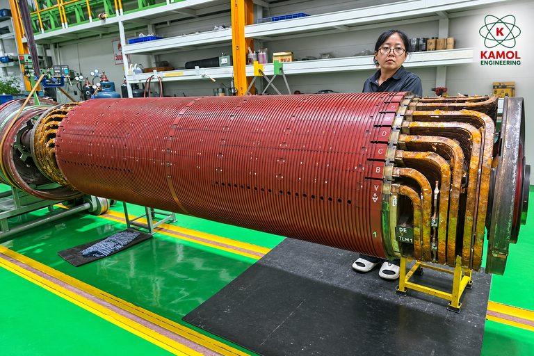
On the workshop floor, a large cylindrical rotor rests horizontally on its supporting equipment. Long rows of winding-related components run along the rotor body, while formed conductor end turns are visible at the ends.
It is the kind of equipment that demands careful planning before anyone begins removing or replacing winding components.
With a machine rated at 15,000 kW, two poles and 6,600 V, the repair involves more than the electrical condition of the winding. Engineers also need to consider conductor geometry, insulation, mechanical restraint and the forces the rotor will experience in operation.
A replacement winding may look correct when installed, but appearance alone cannot confirm that its design, insulation or supporting components meet the requirements of the machine.
The quality of a large rotor rewind depends on understanding the original winding, controlling the installation process and verifying the completed work against the correct engineering requirements.
Understanding the 15 MW Rotor Rewinding Requirement
The machine information supplied for this example is:
| Parameter | Reported Rating |
|---|---|
| Rated Power | 15,000 kW (15 MW) |
| Number of Poles | 2 |
| Rated Machine Voltage | 6,600 V (6.6 kV) |
| Machine Type | To be confirmed from nameplate |
| Rated Frequency and Speed | Not provided |
These ratings establish the reported scale of the machine, but they do not provide a complete rotor winding specification.
For example, 6.6 kV is the reported machine voltage. It should not automatically be treated as the voltage applied across the rotor winding.
The rotor circuit, insulation requirements and appropriate electrical test methods depend on the actual machine design.
What Does the Two-Pole Rating Tell Us?
Two-pole machines are commonly associated with high rotational speeds.
At 50 Hz, the synchronous speed of a two-pole machine is 3,000 rpm. At 60 Hz, it is 3,600 rpm.
However, those figures are synchronous speeds, not confirmed nameplate speeds for this particular machine.
A synchronous machine operates at synchronous speed under normal synchronized conditions. An induction motor normally operates below synchronous speed because of slip.
Without the machine type, frequency and original documentation, it would be inappropriate to publish a specific rated operating speed for this rotor.
Before Rewinding, Understand the Original Rotor
A rotor winding does not exist independently of the rest of the machine.
Its conductors, insulation, connections and mechanical support form part of an integrated design. Changing one element without understanding the others can introduce problems that were not present before the repair.
For that reason, documenting the original condition is a critical part of repair planning.
Preserving the Original Winding Information
Depending on the rotor design, engineers may need to record:
- Conductor size and construction
- Coil shape and arrangement
- Number of turns and winding connections
- Slot dimensions and conductor positions
- Insulation thickness and construction
- End-winding geometry
- Supporting and retaining components
- Signs of wear, contamination or overheating
Original manufacturer drawings and winding records should be used when available.
If information is recovered from a damaged winding, it should be checked against other evidence before being accepted as the basis for replacement work.
Why Documentation Before Removal Matters
Some winding details become difficult to reconstruct after the original conductors and insulation have been removed.
Photographs, dimensional records, connection diagrams and component identification can help preserve information that would otherwise be lost.
Good records are also useful when engineers need to explain which parts were replaced, which were retained and which conditions were discovered during disassembly.
Coil Geometry and Installation Accuracy
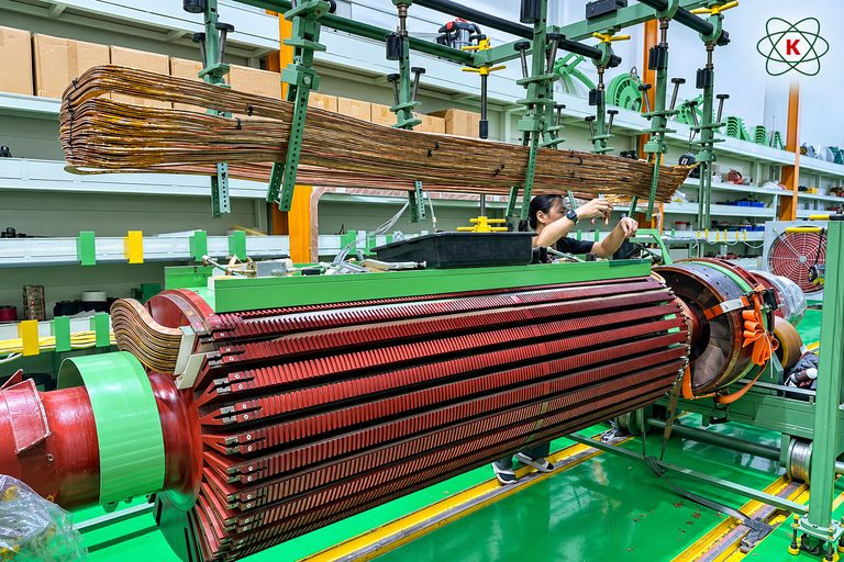
One of the most demanding parts of rotor rewinding is making sure the winding components fit the actual rotor geometry.
Large formed conductors cannot simply be pushed into place because they appear close to the required shape.
Their dimensions, insulation build and relationship to surrounding components must follow the approved winding design.
Why Coil Fit Is So Important
A winding component that does not fit correctly may create unwanted mechanical pressure, reduce the intended insulation clearance or interfere with retaining components.
Those problems are not always visible once the assembly is complete.
Checking coil geometry before and during installation helps identify dimensional issues while they can still be addressed.
Handling Large Winding Components
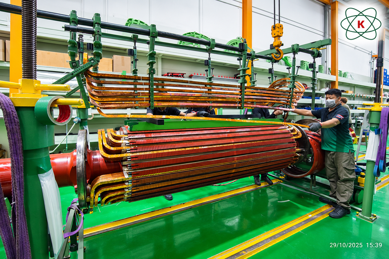
The size and shape of a conductor assembly can make handling difficult.
Suitable supports and lifting arrangements should be selected to avoid excessive bending, uncontrolled movement or damage to the insulation.
The exact method depends on the component’s mass, geometry and the approved handling procedure.
Insulation should be inspected after handling as well as before installation, particularly where conductors pass close to slot edges or other structural components.
Rotor Insulation Must Suit the Actual Winding Design
Insulation is one of the most important parts of any winding repair, but its requirements are not determined by machine terminal voltage alone.
The insulation system must be selected for the actual rotor circuit, conductor arrangement and expected operating conditions.
Depending on the design, the system may include insulation between turns, separation from grounded components, protection at connections and insulation where conductors pass through the rotor structure.
Material selection and processing requirements should follow the approved engineering specification.
Electrical Insulation and Mechanical Support Work Together
During operation, rotor winding components experience mechanical forces as well as electrical and thermal stresses.
For a high-speed rotor, conductor retention and end-winding support deserve particular attention.
Where applicable, wedges, retaining components and other restraints should be assessed for condition and suitability.
The correct arrangement depends on rotor construction. A method appropriate for one rotor design may not be suitable for another.
It would therefore be misleading to recommend the same insulation or retaining arrangement for every two-pole rotor.
Why In-Process Inspection Matters
A final inspection is important, but it cannot replace checks made while the winding is being installed.
Some areas become difficult to access once additional conductors, insulation and retaining components are fitted.
Inspection during assembly can help verify that the work is progressing according to the approved design.
Useful Inspection Points During Rewinding
- Conductor dimensions before installation
- Condition of insulation surfaces
- Rotor slot condition and cleanliness
- Conductor seating and alignment
- Connection locations and routing
- End-winding supports and clearances
- Condition of retaining components
- Photographic records of critical stages
Acceptance criteria should come from the machine-specific repair specification. A general inspection checklist does not establish whether a component meets its required dimensions or electrical properties.
What Should Be Checked After Rotor Rewinding?
The completion of winding installation is not the same as completion of the entire repair.
Further checks may be needed to establish whether the assembly meets the agreed requirements.
Depending on machine construction and the work performed, these may include electrical measurements, insulation assessments, connection checks, mechanical inspections and review of the winding retention system.
Rotor balancing may also require assessment as part of the repair scope. The need and method depend on the machine and the work performed.
Test methods and test voltages must be selected for the actual rotor circuit and its condition. A procedure suitable for a stator winding should not automatically be applied to a rotor winding.
Repair Records Are Part of the Engineering Result
A useful completion record should identify what work was performed, which checks were made, the conditions under which testing took place and the criteria used to evaluate the results.
It should also make clear which items were outside the agreed repair scope.
No test results or acceptance outcomes are assumed for the rotor shown in the supplied photograph.
Five Questions to Ask Before Approving a Large Rotor Rewind
Maintenance and reliability teams do not need to review every winding detail themselves. However, they should understand the evidence behind the proposed repair.
1. Has the Original Winding Been Documented?
The repair team should be able to explain how the original winding arrangement was identified and verified.
2. Is the Replacement Winding Design Confirmed?
Conductor geometry, insulation and connections should be linked to an approved design or an appropriately reviewed engineering specification.
3. How Will Installation Quality Be Checked?
The repair plan should identify inspections carried out before access to critical areas becomes restricted.
4. Are Mechanical Retaining Components Included in the Assessment?
The winding must remain appropriately supported during operation. The condition and suitability of relevant restraints should not be overlooked.
5. Which Final Tests and Acceptance Criteria Apply?
Verification should be specific to the rotor type, winding circuit and repair scope.
Good Rotor Rewinding Is About More Than New Copper
A large rotor rewind brings several disciplines together.
There is electrical engineering in the winding arrangement and insulation system. There is mechanical engineering in how the conductors are retained. There is workshop practice in how heavy components are handled. And there is quality control in the records and inspections that support the finished work.
The photograph supplied for this article illustrates the scale and detail involved in working on a large rotor.
What determines the quality of the repair, however, is not the appearance of the winding alone. It is whether the completed work meets the appropriate engineering requirements for the actual machine.
Discuss Your Rotor Rewinding Requirements With Kamol Engineering
Kamol Engineering Services Co., Ltd. provides rotor rewinding services for rotating electrical machines.
If you are preparing an enquiry for a large rotor, useful information includes the machine nameplate, rotor photographs, available drawings, existing winding records, operating history and the proposed repair scope.
These details can help establish the questions that need to be addressed during technical review.
Explore Rotor Rewinding Services
Frequently Asked Questions
What is rotor rewinding?
Rotor rewinding is the repair or replacement of electrical winding components in the rotating part of an electrical machine. The work method depends on the rotor design, condition and repair specification.
What is important when rewinding a large two-pole rotor?
Engineers need to consider the original winding design, coil dimensions, insulation, mechanical support and the operating conditions of the machine. The appropriate checks depend on its actual construction.
Does a 6.6 kV machine have a 6.6 kV rotor winding?
Not necessarily. The machine’s terminal voltage does not establish the voltage across the rotor winding. The correct rotor electrical requirements depend on the machine type and circuit design.
What is the speed of a two-pole rotor?
The synchronous speed is 3,000 rpm at 50 Hz or 3,600 rpm at 60 Hz. Actual rated operating speed depends on frequency, machine type and design. The nameplate should be checked before stating a project-specific speed.
Why is original winding data important?
Original winding data helps establish conductor dimensions, coil arrangement, insulation construction and connections. It provides a basis for planning and checking the replacement work.
Which tests are required after rotor rewinding?
Testing depends on the rotor type, winding circuit and repair requirements. Qualified personnel should select appropriate electrical and mechanical checks and evaluate the results against agreed acceptance criteria.
Technical References
EASA — ANSI/EASA AR100-2025: Recommended Practice for the Repair of Rotating Electrical Apparatus
EASA — Wound Rotor Repair Tips: Testing, Application and Failure Analysis
Kamol Engineering — Rewinding Rotor
Editorial note: The 15,000 kW, two-pole and 6,600 V ratings were supplied by the project owner. Machine type, frequency, actual rated speed, winding circuit, repair stage and test results have not been independently verified. The original photograph illustrates workshop equipment but does not establish completed repair acceptance. Engineering and testing requirements must be determined for the specific machine.